技術專欄
EstiNet11 x P4 Switching Research
EstiNet11 now supports P4 (Programming Protocol-Independent Packet Processors) switching research. It is also capable of loading Docker containers that run P4 Bv2 simultaors into a simulated network. A container that runs BMv2 simulator can simulation the network operation of a state-of-the-art P4 switch and users can run its own P4 switching codes on each specific container.That's a large P4 network with time clocks controlled and synchronized can be easily created on EstiNet11 platform. There is an example which introduce how to use P4 container on EstiNet11 platform..
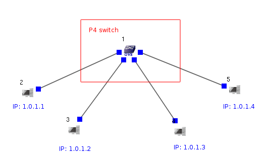
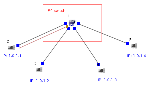
In this example, we will use the same topology for two kinds of progressing mode. One is example A “Run as Fast as Possible” the other is example B “Try to Synchronize with the Real-world Clock”. For sample B, user could set commands when simulation be executed.
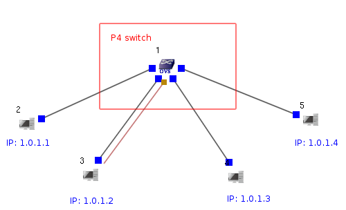
Please select Node  Open vSwitch to build a topology in EstiNet X platform. Or extract a compressed file P4_l2_switch_example.tar.bz2. There are two examples P4_l2_switch_exampleA and P4_l2_switch_exampleB in this compressed file. Please open file [P4_l12_switch_exampleA.xtpl] firstly.
(1) Set the Duration of Simulation
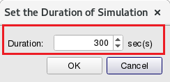
Set the duration of simulation
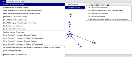
From E-Tools => Configure Simulation Processes => Simulation Engine => Set the Duration of Simulation
Setting Duration time as 300 sec(s) in this example.
(2) The settings of P4_l2_switch_exampleA
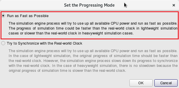
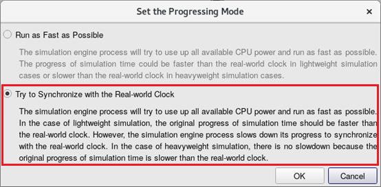
From E-Tools => Configure Simulation Processes => Simulation Engine => Set the Progressing Mode
Select “Run as Fast as Possible”.
In  E status (Edit Parameters), double click Node1
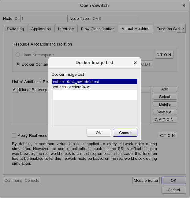
  Open vSwitch and select Tab Virtual Machine. Click Docker Container and select estinet11/P4 switch in “Resource Allocation and Isolation”.
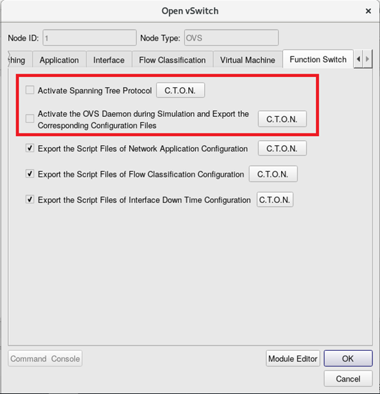
Disable Spanning Tree Protocol and OVS Daemon in Tab Function Switch as below figure.
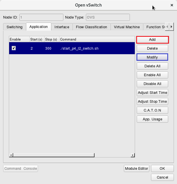
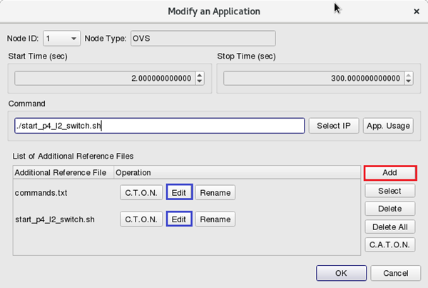
Click Tab Application and add the startup command ./start_p4_l2_switch.sh for P4 switch. It also need to add script files start_p4_l2_switch.sh and commands.txt in the field of “List of Additional Reference Files”. (If users use exampleA, they could click Modify or Edit to check the settings.)
The content of P4 switch startup script file (start_p4_l2_switch.sh):
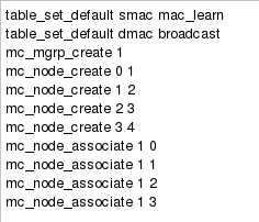
The content of self-defined P4 switch command file(commands.txt):
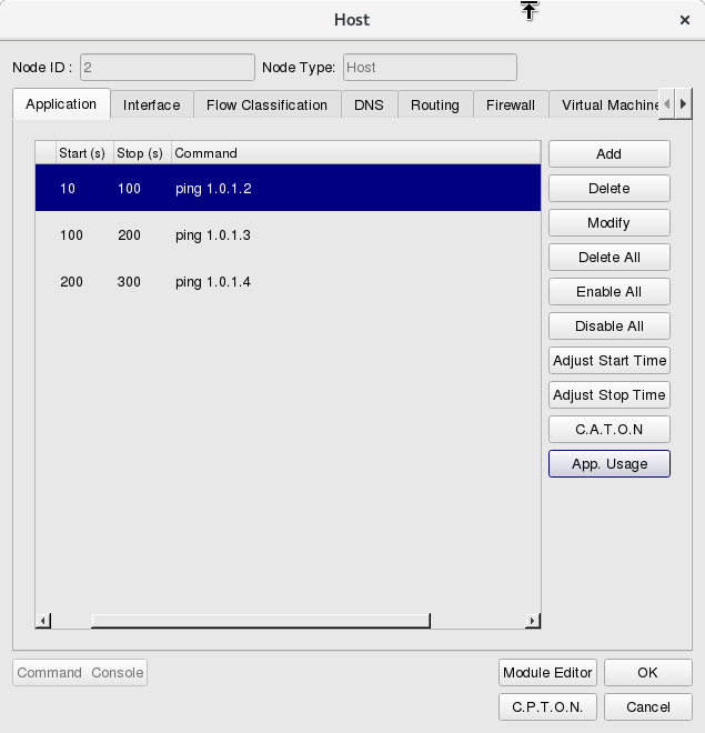
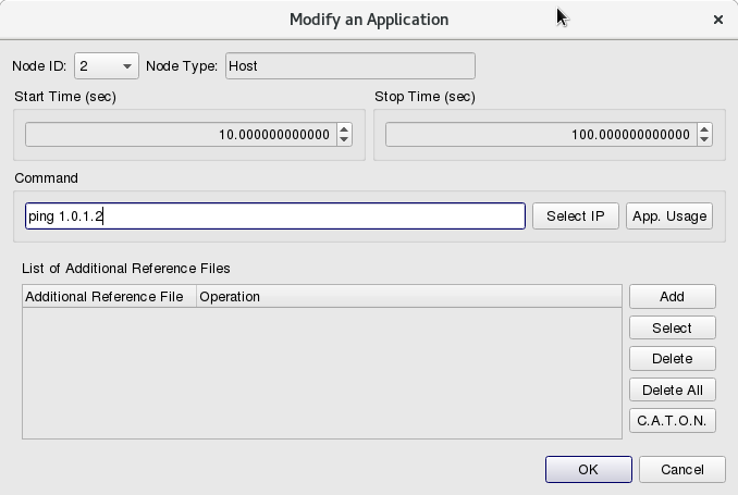
In Node2  Host, click Tab Application to set the traffic as
- Simulation Start Time: 10 secs, Stop Time: 100 secs, from Node2 (1.0.1.1) to ping Node3 (1.0.1.2)
- Simulation Start Time: 100 secs, Stop Time: 200 secs, from Node2 (1.0.1.1) to ping Node4 (1.0.1.3)
- Simulation Start Time: 200 secs, Stop Time: 300 secs, from Node2 (1.0.1.1) to ping Node5 (1.0.1.4)
Transfer to  G status (Generate Configuration Files) Click Run-Panel => Start Simulation to start a simulation from Tool Bar.
After simulation finished, the simulator will transfer to  P status (Play Back Results) directly. Users could click button Play
 ![]() to observe the packet flow.
to observe the packet flow.
(3) The settings of P4_l2_switch_exampleB
Please open example file [P4_l2_switch_exampleB.xtpl]
From E-Tools => Configure Simulation Processes => Simulation Engine => Set the Progressing Mode
Select “Try to Synchronize with the Real-world Clock”.
In  E status (Edit Parameters), double click Node1
  Open vSwitch and select Tab Virtual Machine. Click Docker Container and select estinet10/P4 switch in “Resource Allocation and Isolation”.
Disable Spanning Tree Protocol and OVS Daemon in Tab Function Switch as below figure.
Transfer to  G status (Generate Configuration Files). Click Run-Panel => Start Simulation to start a simulation from Tool Bar.
- When simulation time was increased
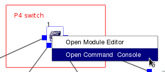
 which was at the left button corner of simulation platform after start a simulation, users could click right button of mouse and select Open Command Console.
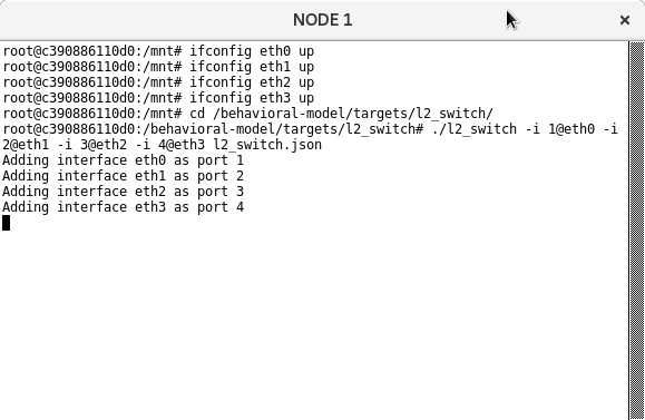
- Please input below commands to startup P4 switch daemon
#ifconfig eth0 up
#ifconfig eth1 up
#ifconfig eth2 up
#ifconfig eth3 up
#cd /behavioral-model/targets/l2_swtich
/behavioral-model/targets/l2_swtich# ./l2_swtich -i 1@eth0 -i 2@eth1 -i 3@eth2 -i 4@eth3 l2_switch.json
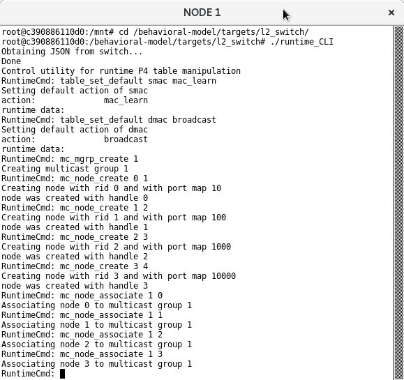
- Please open another window of Command Console to input below commands which will startup P4 switch CLI that settings the learning and broadcast domain of switch.
#cd /behavioral-model/targets/l2_swtich
/behavioral-model/targets/l2_swtich# ./runtime_CLI
RuntimeCmd: table_set_default smac mac_learn
RuntimeCmd: table_set_default dmac broadcast
RuntimeCmd: mc_mgrp_create 1
RuntimeCmd: mc_node_create 0 1
RuntimeCmd: mc_node_create 1 2
RuntimeCmd: mc_node_create 2 3
RuntimeCmd: mc_node_create 3 4
RuntimeCmd: mc_node_associate 1 0
RuntimeCmd: mc_node_associate 1 1
RuntimeCmd: mc_node_associate 1 2
RuntimeCmd: mc_node_associate 1 3
After complete above steps, users could send packets in this topology.
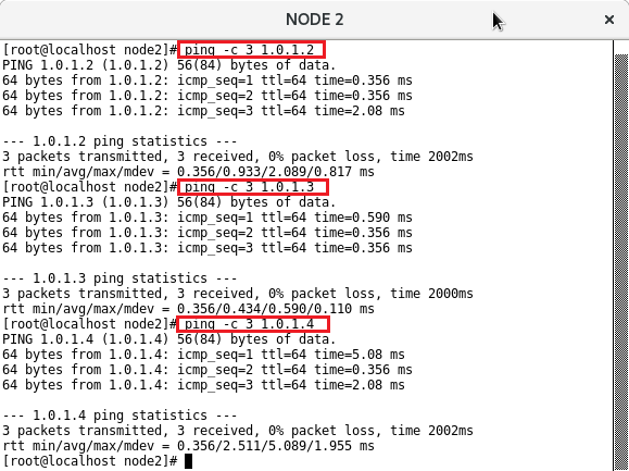
Open a command console on Node2 Host and try to execute ping command to Node 3 (IP: 1.0.1.2).
#ping –c 3 1.0.1.2
Then to Node 4 (IP: 1.0.1.3).
#ping –c 3 1.0.1.3
And to Node 5 (IP: 1.0.1.4).
#ping –c 3 1.0.1.4
Users could observe packet transfer successfully from command console window. This means P4 switch already execute L2 switch function successfully.
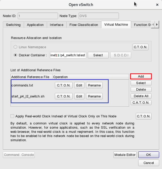
The operation way of the exampleB needs to input many commands when simulation. It’s really not convenient for users. There is another method to reduce input commands. After double click Node1  Open vSwitch and select Tab Virtual Machine, click Docker Container and select estinet10/P4 switch in “Resource Allocation and Isolation”. Besides this, the field “List of Additional Reference Files” in the same page could add two files start_p4_l2_switch.sh and commands.txt as below figure.
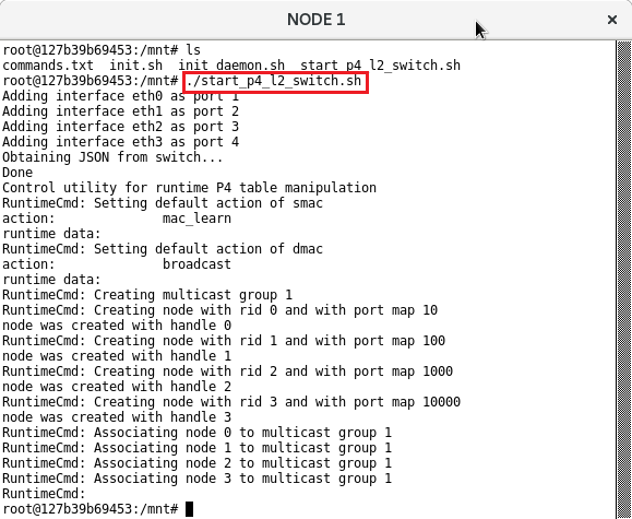
With this setting, after Start Simulation, users could only execute command#./start_p4_l2_switch.sh under Command Console of Node1 P4 switch.
Then users could try to send network traffic in this topology such as from Node2 to ping Node3, Node4 and Node5 with the same way.
If users would like to try the example, they should update the EstiNet installation package which include the docker container of P4 switch in EstiNet simulator. Please reference 4. How to use P4 Switch in EstiNet Simulator from document VMImage Installation Guide for more details.

